Thursday, March 30, 2017

Mercedes Bosch D-Jetronic Wiring


The early Mercedes 450SL was fitted with the Bosch D-Jetronic, EFI or Electronic Fuel Injection system. While this blog post will not cover in detail the entirety of the D-Jet system, it will cover all the steps for a full removal in preparation for an inspection and refurbishing of the harness. This will be covered in a future article. 

It is a good idea if you own or are in the market for a Mercedes 450SL or any classic Mercedes, to either regularly inspect or throughly inspect the car respectively. As our cars age, much of the rubber, plastic, and wiring is in poor condition and needs to be either replaced or repaired. Don't risk a fire!

Removing the EFI - D-Jet wiring, is not complicated, does not require any special tools, but will require some physical contortion. As is indicated throughout the car used for this blog is a 1975 450SL. The wiring will vary depending on chassis series.

STEP 1
DISCONNECT BATTERY!

STEP 2
Remove air cleaner and the plug to the air temp sensor. While in the process, check the seal on the underside of the air cleaner housing. This is the seal between the air cleaner and throttle body. This seal is still available from Mercedes-Benz. TIP: When purchasing a new seal, make sure it is for the D-Jet. The later K-Jet will not fit. 

STEP 3
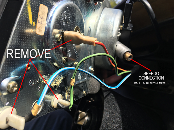
Label every wire and take photos before removing any thing. I use masking tape looped around the wire and stuck to itself with a piece long enough to write on with a Sharpie. 

STEP 4
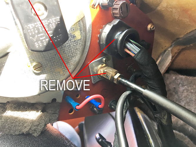
Unplug the wires from their respective terminals but leave harness in place. Check all terminals for damage as you unplug each wire
Throttle Position Sensor (Shown: 1975 450SL)

Intake minifold sensor—passenger side (Shown: 1975 450SL)
Harness ground wires (Shown: 1975 450SL)


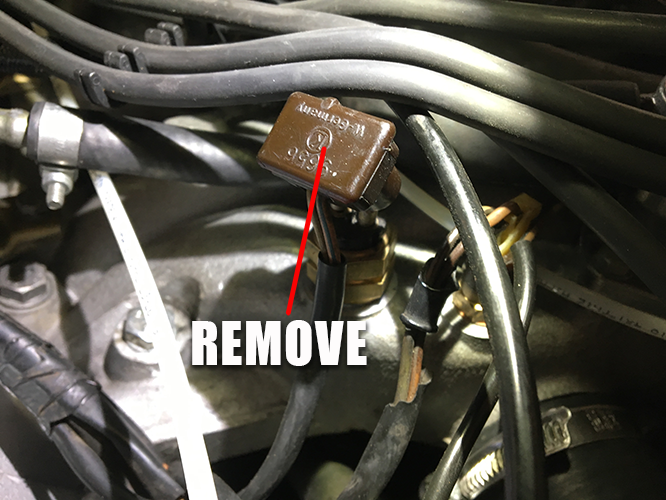
Thermo Time Switch (Shown: 1975 450SL)


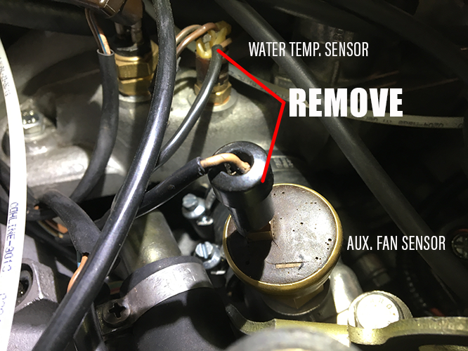
Water Temp. Sensor and Auxiliary Fan Sensor (Shown: 1975 450SL) NOTE: Depending on the chassis series, the Aux. Fan Sensor and driver side manifold temp sensor were wired independently from the main harness.


Cold Start Fuel Injector (Shown: 1975 450SL)


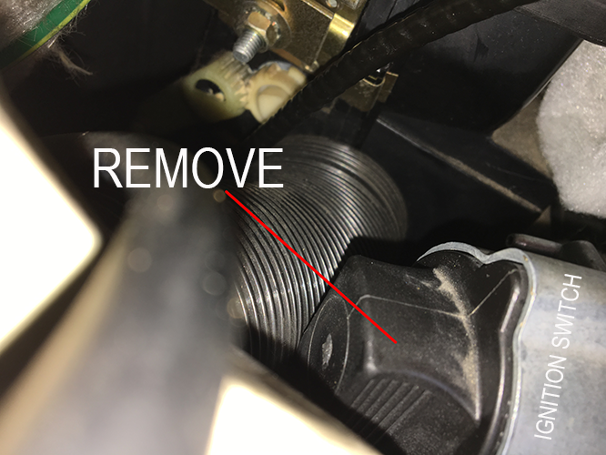
Plug to distributor (Shown: 1975 450SL)


Remove bracket and receptacle (lower half of photo above) (Shown: 1975 450SL)


Manifold Pressure Sensor (MPS) under master cylinder (Shown: 1975 450SL)


Unplug all 8 fuel injectors and be sure to label (Shown: 1975 450SL)


STEP 5
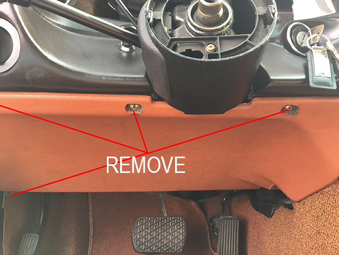
Remove the lower passenger side footwell dash panels and locate the ECU under the dash as shown in photo below.

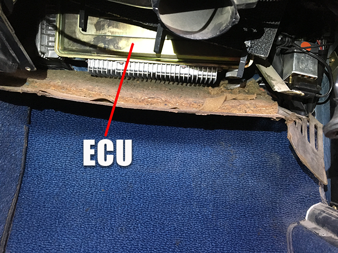
ECU under passenger side dash area (Shown: 1975 450SL)


STEP 6
Remove the lower spring clip by pulling down on it. The hinge of the clip is attached to the firewall. Once the lower clip is removed, gently wiggle the ECU back and forth while pulling down to release the flanged retaining peg from the upper bracket.

When the ECU is free, remove the plastic harness plug guard (not shown) and the wiring harness retention collar (illustrated below) to release the harness wire and unplug the harness. 


Illustration above shows how the ECU is held in place. (Image curtesy of Mercedes-Benz


STEP 7
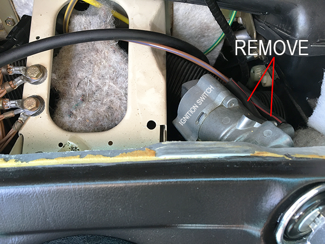
Unplug both relay connectors and single line plug. Should one of your plug housings break, they are available from Mercedes.


Harness plugs under dash (Shown: 1975 450SL)


STEP 8
Release the rubber grommet from the firewall. It will more than likely not survive the removal and will require renewal. They are are still available through Mercedes for $80. NOTE: It is not necessary but will make the job easier to remove the valve cover.

Harness firewall grommet (Shown: 1975 450SL)

STEP 9
With help, pull the wire through the firewall. It is best to have one person in the car guiding while the other pulls from the engine bay side.

STEP 10
Remove entire wiring harness from engine compartment and your done, at least with the first part.


In my next blog, we will cover the inspection and restoration of the harness.


Thursday, February 23, 2017

Mercedes Gauge Needle Painting & Restoration

Mercedes-Benz Gauge Cluster Needle Painting and Gauge Face Cleaning

NOTE: The gauge cluster and gauges shown in this blog are from the Mercedes W116 and 107 chassis. The W123 instrument cluster is very similar, but there are some differences in the disassembly process of the housing. The W123 specific housing restoration will be covered in a later article. 

There are numerous ways to refinish faded or dirty indicator needles on a gauge and clean the gauge face, but great care must always be taken to avoid making matters worse. The following step-by-step is simply my preferred method for the process. Only do what you feel comfortable with based on your particular circumstances and experience level.

Take your time and properly prep any surface to be refinished, but always be aware of what can and can't be used as a cleaning agent! Some cleaning agents will destroy, while others will do nothing. It is best to start with the least aggressive cleaning method and work your way up as needed.

For this project, I recommend having the following "tools":

Distilled Water
Cream of Tarter
Construction Paper
Masking Tape
Petrolium Jelly
Cotton Swabs
Microfiber Cloth
Rubbing Alcohol 
Hobby/Model Spray Paint (I used Krylon Short Cuts - Glow Orange)

STEP 1
For the purpose of this blog, we will begin with the gauges already removed (For instructions on gauge cluster removal from dashboard, visit my blog "W123 Ignition Switch and Lock" posted Feb. 18, 2017. A subsequent article will cover a complete disassembly of the cluster housing for cleaning.


STEP 2
DO NOT do proceed to the following steps and consult a professional If gauge face finish is cracked, chipped or is in any other manner deteriorating!

Typically the gauge face should only be lightly dusty and need just a gentle wipe with a microfiber cloth. If however the the printing (numbers etc.) or background paint is grungy, the following will likely help to clean the surface quite well.

First, mix about 1 level teaspoon cream of tarter (available in the spice or baking section at any grocery store) in a small container and add just enough distilled water (must be distilled) to make a paste—it should not be runny.

WARNING: Always test along very edge of gauge face that is not seen when installed. Apply adequate amount of the cream of tarter paste to the face surface and gently agitate over the entire surface with fingertip. DO NOT allow paste to enter the gauge mechanism. Remove paste with an unused microfiber cloth that is slightly dampened with distilled water until all traces of the paste is gone and lightly buff for final stage. Should any dirt remain, attempt one additional cleaning. If still no success, it would be advisable to contact a professional in the field for further assistance. Generally however, the cream of tarter paste works excellently should it even be needed. FYI, the cream of tarter method came on recommendation from a jeweler who restored vintage clock and watch faces. I have also cleaned a number of gauge faces using this method with excellent results.

STEP 3
Throughly cover entire face and sides of gauge with construction paper and tape. All seams in the construction paper must be sealed and the sides of the gauge must be sealed as well. When spraying, the smallest gap will allow spray paint to penetrate and potentially ruin the finish. At this stage, also clean needles gently with rubbing alcohol. Lightly dampen cotton swab with rubbing alcohol and gently rub needle until no traces of dirt can be removed. If color is just being removed, surface should be sufficiently clean to paint. Allow to air dry for about 5 min. before painting.


STEP 4
Now coat needle centers liberally with petroleum jelly. Apply to top and entire edge—any where you do not want paint to remain. Be careful however, not to touch the needle with any petroleum jelly as it will cause paint not to stick. Photo below shows gauge ready for paint.


STEP 5
Spray needles from all angles using very quick passes from 6-8 in. away. DO NOT over coat needles. Paint will cover needles very quickly. Be sure however to examine your work closely from all angels. Check for even coverage before removing masking. If a spot was missed, DO NOT attempt to just spray paint the missed area. Spray the general area as before, to keep an even coat. Allow to dry for about 5 minutes.

STEP 6
After about 5 minutes, use a clean dry cotton swab and gently rub needle centers to remove paint. Do not touch needle as they may still be tacky and attract lint particles from the cotton swab. As you can see, the paint is easily wiped away, leaving a perfectly clean surface. When the paint is completely removed, moisten a clean cotton swab with rubbing alcohol and wipe down needle centers to remove all traces of grease. Any remaining grease will attract dirt over time.


STEP 7
If you are spraying needles in low humidity as I was, the spray paint can tend to begin drying on the way to the surface, causing flecks of paint on the edges as shown by the yellow circles. Should this occur, use a toothpick and very gently run it along the effected area to remove. Wait however until the paint is fully dry to do this.


STEP 8
Take a final look at the work and you are done. For any lint that may be on the face of the gauge, use low pressure shop air to remove.

NEXT STEPS
I highly recommend at this stage to disassemble and clean the gauge cluster housing. Don't put your beautiful gauges back into a dirty case. My next blog article will focus on the cleaning and overhaul of the housing. If you're going to do it, do it right!

You can see what a difference a cleaning and repaint of the needles can do. The photo below is of the gauge in step 3, now ready for installation. You will also notice from the photo in step 1 how faded the needles were after 42 years. These particular gauges are from my 1975 Mercedes 450SL but the process of cleaning and painting is identical for the W123 and many other models.


Saturday, February 18, 2017

W123 Ignition Switch and Lock

How to Replace a Mercedes W123 Ignition Switch

This blog will focus on the removal and/or replacement of the later model, (from chassis No. 208267) W123 ignition switch (7 pin) and lock housing assembly and lock. Note: Chassis 208266 and earlier requires a different ignition switch (8 pin) assembly.

Always check your VIN for the chassis number prior to ordering any parts. The chassis number is the last 6 digits of the VIN.

TIP: Before you start, I recommend taking photos each step of the way so you remember exactly how everything goes back together. Loose parts can accumulate quickly and losing track of what went where, is easy to do.

STEP 1
DISCONNECT THE BATTERY! This is a good habit to get into when undertaking numerous jobs on your car.

STEP 2
Remove steering wheel center emblem. Gently pry plastic star ornament from center of steering wheel. Use a small trim removal tool. Note: Be careful not to scratch the back on removal as it will remove the blackout and or silver star coating. This plastic is clear and and simply panted on one side.


STEP 3 
Remove steering wheel bolt using a 10mm hex socket. DO NOT use steering wheel lock to hold the steering wheel while attempting to loosen the bolt. Doing so can result in damaging the lock mechanism. To keep the lock from engaging, turn key to position "I". It may be necessary to have another person holding the steering wheel while a breaker bar with an 8 in. extension. There is no need to remove the horn pad for this procedure. An impact wrench can also be used for quick and easy removal.


STEP 4
Remove steering wheel. Before doing so however, mark steering wheel and hub with pencil or marker to insure wheel is returned to the centered position.


STEP 5-1
Remove gauge cluster. Withdraw by means of Mercedes tool No.140 589 0233 00 shown, or by reaching up from under the dash and pressing it out from the back (steps for removal of the lower dash panel next). Pulling the cluster out more than a few inches will not be possible until the speedometer cable has been removed. Once speedometer cable has been removed, the main electrical, clock, two light bulbs and the oil pressure line will also need to be removed.


STEP 5-2
Remove wiring from cluster as shown.


STEP 5-3
Remove remaining wiring as shown. Main connector, oil pressure line and speedometer plug.


STEP 6
Remove lower dash panelling. Remove the three screws holding the panel to the facia along with the gray plastic locking "screw" from near the emergency brake pedal. 


STEP 7
Remove the two vacuum lines from ignition housing (diesel models only). Mark lines to be sure they are returned to the correct port on reinstallation.


STEP 8
Remove chrome trim ring from ignition key tumbler housing on dashboard. Remove very gently with small plastic trim removal tool. The three retaining clips can only handle a few removals before they break off, rendering the ring useless. Photo shows trim ring removed.


STEP 9
Remove lock tumbler by turning key clockwise to the "accessory" position. Next, insert a strong wire such as a paperclip or similar sized wire. This wire will act as a secondary "key". It is very helpful to file a 45ยบ angle on the tip of this wire for easy of insertion. The wire should be no shorter than 3 inches for ease of use. Insert wire as shown until it stops. Next, loosen and remove the black tumbler housing by turning counter clockwise until fully loose. NOTE: If the tumbler housing does not turn, the wire has not been properly inserted. At this stage, the key, tumbler and tumbler cover can be removed as a unit. To separate the tumbler from the housing and key, hold the back of the tumbler assembly with your finger and turn the key to position "1" and with draw key. NOTE: The wire "key" must remain in place during the entire process until the tumbler, etc., has been removed. Reinstallation is the revers of this process.

LOCK TUMBLER REPLACEMENT ONLY
If you are just in need of replacing the lock tumbler, this step, "STEP 9" would be the only step necessary for the job. NOTE: If the lock ever begins to not function smoothly, replace it at once. Many older Mercedes end up having to have the locks drilled out.


Image below shows tumbler and assembly removed


STEP 10
Remove ignition switch plug. Gently wiggle it loose. It is tight up against air ducts and the steering column brace. Although there are finger grips as the photo shows, it is nonetheless firmly seated.


STEP 11
Remove seatbelt warning buzzer plug (USA models only). This plug is located on the under side of the ignition lock housing and can only be accessed from under the dash.


STEP 12
Loosen steering column ignition housing clamp bolt. 5-6 full turns should be sufficient to withdraw lock housing. 


STEP 13
Depress ignition lock housing anti-theft "button". I used a nail punch to depress the button, but any similar sized object will suffice. It does not require any force and will only depress about 1 or 2mm. While depressing the "button" wiggle the ignition lock housing outward from the column sleeve. Once the lock housing has been moved outward but a few millimeters, the anti-theft button can be released. Continue to withdraw the lock housing in the out ward and upward direction. The housing will ultimately come out through the cluster gauge opening. NOTE: Do not force! It is a snug fit and the dash board can very easily be damaged around the ignition key area. Remember the dashboard material on these older cars is no longer very forgiving and will crack and crumble very easily.


STEP 14
Remove the three recessed ignition switch retaining screws and withdraw switch. The new ignition switch has a tab on one side that will align with a groove on the housing to avoid improper installation. 

While this process may appear overly complicated for such a simple part, it is unfortunately necessary. Consider however, it probably won't need to be done again for another 30+ years.

Now, simply reverse the process to complete the job.